| |
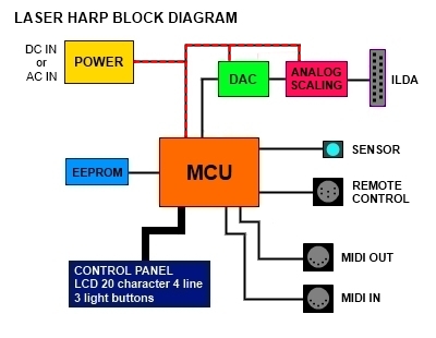
Block diagram
|
The laser harp power supply is designed for 8 to 30v DC or integrated 90-240v AC (optional) power input.
The MCU (Micro Controller Unit) run the laser harp program, that's the firmware. Its internal EEPROM holds all the features.
The control panel provide a display of 4 lines, 3 backlit buttons and 1 potentiometer.
The EEPROM stores data tracks, up to 20 tracks - 20 beams - 5 notes by beam and data playlists, up to 10 playlists - 40 tracks.
The remote control switches the previous/next track or the opening/closing frame or the musical banks or swithing octave +/- (x3).
The sensor is the main unit, lot of search about it, we must get less disturbance of the ambient light for the sensor trigger.
The ILDA need a analog electric signal to get a full color laser and moved the miror scan engine.
The MIDI connectors in input and output append a link to a synthesizer or a sampler:
- input to record the notes, the patterns and the banks;
- output to send the notes or the patterns and to switch the bank.
|
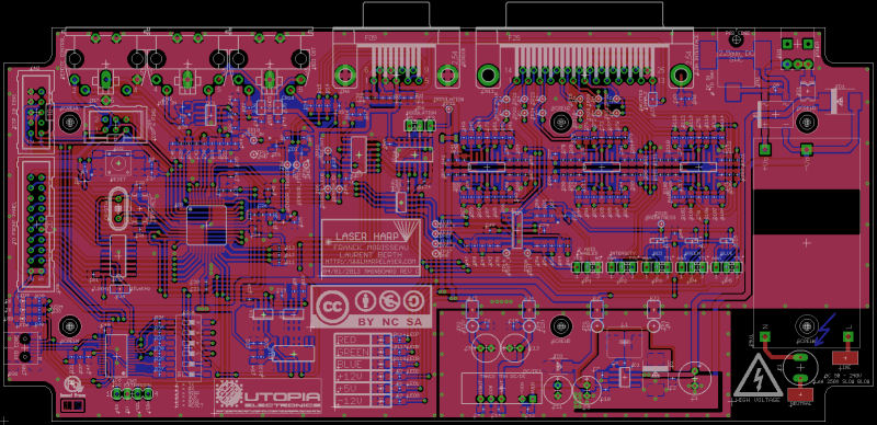
Electronic boards
The hardware design has four electronic boards:
- the motherboard holds the microcontroller, the connectics and the power supply.
- the control panel holds the LCD panel (20 characters x 4 lines), 3 backlit buttons and 1 potentiometer.
- the sensor trigger holds the photodiode capable of converting light into either current or voltage.
- the remote control holds the 4 backlit pedals.
|
|